
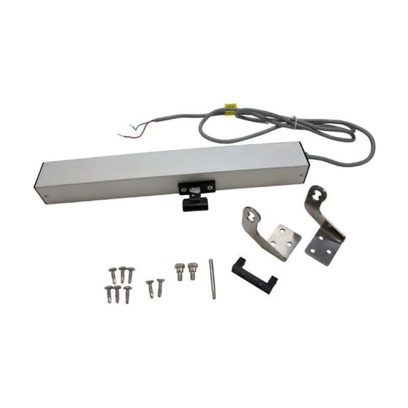
An electric chain actuator is quickly installed – what matters for reliable operation is the correct connection. This guide shows the difference between 24 V and 230 V actuators, how to choose cable cross-section and control unit, and which wiring mistakes are common.
24 V or 230 V: two connection principles
| 24 V drive | 230 V drive | |
|---|---|---|
| Supply | via power supply or control unit (24 V DC) | directly from the building installation |
| Change of direction | by reversing the polarity of the two wires | separate wires for OPEN and CLOSE |
| operation | control unit with switch, radio or sensors | Ventilation switch OPEN/CLOSE |
| Several windows | together via one control unit | individually or via group control |
| RWA | standard for SHEV control panels | not for SHEV control panels |
When which voltage makes sense is explained in the guide Window actuator 24 V or 230 V.
Connecting a 24 V chain actuator
A 24 V actuator has two wires. The direction of travel is changed by reversing the polarity: with plus on one wire the actuator opens; if the polarity is swapped, it closes. The end-of-travel cut-off is inside the actuator.
- Disconnect the power supply.
- Route the actuator cable to the control unit or junction box.
- Connect the wires to the motor output of the control unit according to the instructions.
- Test run: if the actuator closes on OPEN, swap the two wires.
The control VS-C24-7A converts 230 V to 24 V and supplies up to seven VS-KA 250/400 actuators in parallel. It also supports switches, radio remote control and a wind-rain-light sensor.
Connecting a 230 V chain actuator
230 V actuators are connected via a ventilation switch with separate contacts for OPEN and CLOSE, for example the VS-LT 230 ventilation switch. The wires for OPEN, CLOSE and neutral are connected according to the actuator instructions.
- Work on 230 V may only be carried out by qualified electricians.
- Never activate OPEN and CLOSE at the same time.
- Observe the rated current of the switch when several actuators run on one switch.
Choosing the right cable cross-section
In 24 V systems, voltage drop along the cable is the most common mistake: if too little voltage reaches the actuator, it runs slowly or stops. For copper cables, the cross-section can be roughly calculated as follows:
A = 2 × L × I ÷ (56 × ΔU)
A is the cross-section in mm², L the single cable length in m, I the total current in A and ΔU the permissible voltage drop in V.
Example: three actuators at 0.8 A each (2.4 A total), 20 m cable, 1.2 V permissible voltage drop: A = 2 × 20 × 2.4 ÷ (56 × 1.2) ≈ 1.4 mm². Choose the next larger cross-section, i.e. 1.5 mm².
Common wiring mistakes
- Actuator moves in the wrong direction: wires swapped – reverse polarity for 24 V, swap OPEN and CLOSE for 230 V.
- Actuator runs slowly or stops: cross-section too small or power supply too weak.
- Several actuators run unevenly: for sashes with two actuators, use a synchronous control unit or actuators with synchronisation function such as the VS-KA-i .
- Window does not close when it rains: sensor not connected or set incorrectly.
Frequently asked questions
Can I connect a 24 V actuator directly to 230 V?
No. A 24 V actuator always needs a power supply or control unit supplying 24 V DC. Connecting it directly to 230 V destroys the actuator.
How many actuators can be connected to one control unit?
That depends on the output current of the control unit. Up to seven VS-KA 250/400 actuators can be connected in parallel to the VS-C24-7A.
Do I need an electrician for the connection?
For work on the 230 V installation, yes. 24 V systems should also be installed by qualified personnel.
Support with the connection
Not sure which control unit and cross-section are right? Send us the number of windows and cable lengths – we will help with the design. To the contact form or call +49 40 50694631.